to be continued…
ATTENTION:
Now there is a new integrated IDE that contain CubeMX, ATOLLIC (trueSTUDIO), Library, etc that is recommended to use for new projects and is STM32CubeIDE, see this tutorial.
..
This tutorial is based on the NUCLEO-F401RE that is based on the STM32F401RE but the concepts are valid for all STM32 families.
For more info on Cortex M4 see:
Cortex®-M4 programming manual (PM0214)
For more info regarding the CUBE-MX see:
STM32CubeMX for STM32 configuration and initialization C code generation (UM1718)
- SetUp
- Introduction to the CUBE-MX
- Intro to NUCLEO boards
- Library HAL & LL
SetUp
For follow this training or in general to develop on STM32 families is necessary install on your PC some tools.
Please read my: How to install the toolchain for develop on STM32
Go to on top
Introduction to the CUBE-MX
STM32 CUBE or more precisely CUBE-MX is a graphical tool that allows configuring the STM32 microcontrollers very easily and generate a complete C project for:
IAR, KEIL, AC6 and ATOLLIC.
This platform includes the STM32 Cube Library, ensuring easy portability across STM32 portfolio, plus a consistent set of middleware components (RTOS, USB, FS, TCP/IP, Graphics, etc).
All embedded software examples come with a full set of examples.
With STM32 Cube, STMicroelectronics provides a comprehensive software tool, significantly reducing development efforts, time and cost.
Please read my: CUBE or CUBE-MX tutorial
–
Here I explain how to use:
-
- Configuration tab
-
- RCC
-
- RCC – Costant
-
- RCC – NVIC
-
- Configuration tab
- How to generate a project (in C language)
We use the configuration below, here there is the file ready to use for CUBE-MX.

_
-
- If you go in the Configuration tab
–

–
and click on the RCC button you must see something like below.
–

–
Automatically the CUBE-MX configure the flash wait states according to the Reference Manual of the STM32F401RE.
This is important in case you use the STM32 at different voltage instead of 3,3V.
Try to change the VDD voltage and see what changes.
–
Power voltage scale is a parameter that permit to decrease the consumptions (decrease or increase).
In the RCC – User Constant tab is possible define some constants with a value that we will find in our project.
–

_
In the RCC – NVIC setting tab, is also possible enable the RCC global interrupt.
This is useful if you change the clock speed during the execution of your program.
In this case you get an interrupt at the end of the clock configuration.
–

–
Go back
Go to on top
–
- If you go in the Configuration tab
-
- NVIC – Vector Controller
For default there is active only the System Tick Timer that is use in the HAL library to generate a precise 1mS delay.
Of course it is possible configure the interrupt in according of your application.
Next, during this training, I will show you how to use the interrupts with some examples.
–

–
Go back
Go to on top
- NVIC – Vector Controller
- DMA is used to transfer the data from memory to memory but also from memory to peripherals and vice versa.
I will talk about DMA later in this tutorial.
_
Go back
Go on top
- Power Calculation
For an ever-growing number of embedded systems applications, power consumption is a major concern.
To help minimizing it, CubeMX offers the Power Consumption Calculator tab (see below), which, given a microcontroller, a battery model and a user-defined power sequence, provides the following results:
• Average current consumption Power consumption values can either be taken from the datasheet or interpolated from a user specified bus or core frequency.
• Battery life
• Average DMIPs
DMIPs values are directly taken from the MCU datasheet and are neither interpolated nor extrapolated.
• Maximum ambient temperature (TAMAX)
According to the chip internal power consumption, the package type and a maximum
junction temperature of 105 °C, the tool computes the maximum ambient temperature to ensure good operating conditions.
Current TAMAX implementation does not account for I/O consumption. For an accurate TAMAX estimate, I/O consumption must be specified using the additional Consumption field. The formula for I/O dynamic current consumption is specified in the microcontroller datasheet.
–
 Go back
Go on top
- How to generate a project (in C language)
The C code generated by CubeMX provides user sections as illustrated below.
They allow user C code to be inserted and preserved at next C code generation.
User sections shall neither be moved nor renamed.
Only the user sections defined by CubeMX are preserved.
User created sections will be ignored and lost at next C code generation.
/* USER CODE BEGIN 0 */
(..)
/* USER CODE END 0 */
…
…
/* Infinite loop */
/* USER CODE BEGIN WHILE */
while (1)
{
(..)
/* USER CODE END WHILE */
/* USER CODE BEGIN 3 */
(..)
}
/* USER CODE END 3 */
…
…
–
After you are configured all the peripherals you are ready to generate the project.
For do this select:
Project -> Generate Code
and you must see a window like below.
You must choose the IDE that you need to use and a directory where save your project. Of course, you must also decide a name for your project.For know what means Stack & Heap see my tutorial: Stack & Heap
–

–
Now go in the Code Generator tab and configure the C code generation options:
– The library files copied to Projects folder.
– C code regeneration (e.g. what is kept or backed up during C code regeneration).
– HAL specific action (e.g. set all free pins as analog I/Os to reduce MCU power
consumption).
See below.
–

–
In the Advanced Settings tab, you have the possibility to select HAL library or LL library. Also you have the possibility to generate or not the peripherals function call.
–

–
At the end of your configuration press OK and the code will be generated.
–
If you go in the directory where was saved your project you must see something like below (I used KEIL).
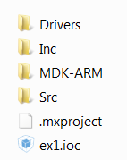
If you go inside the MDK-ARM and click twice on the file ex1.uvproj
immediately start KEIL ready to use with your project.
–

–
If you use a IDE based on AC6 (SW4STM32) or ATOLLIC the procedure to open your project is different, It is necessary import your project in AC6 or ATOLLIC. See this tutorial (from pg.37).
–
Go back
Go to on top
–
Intro to NUCLEO boards
All NUCLEO-xxx include the ST-LINK-v2-1 emulator and receive the power supply from USB connector.
It is also possible use an external power supply.

It is also possible use the ST-LINK-v2-1 to debug an other board, see below.

Go on top
RCC
All peripherals need clock for work.
To do this in the STM32 there is the RCC periphery that share the right clock to the peripherals.
In reality, the RCC give the clock to the internal buses of STM32 which are AHB, AHb1, AHb2, etc. On these buses (see the manual of the STM32 that you use) are connected various peripherals.

Without clock is not possible to change or read peripheral registers.


Go on top