–
This example is born to demonstrate the P2P capability using the SPIRIT1 transceiver and the STprotocol.
This P2P also manage a ACK communication.
This is a basic example from wich is possible implement a loot of application like:

NOTE:
- Use FIREFOX or CHROME for a clear view of the images present in this web site
- For enlarge the image press: CTRL +
For reduce the image press: CTRL –
For make this project we used two kit based on:
— X-NUCLEO-IDS01A4 (Spirit1 at 868 MHz evaboard)
— NUCLEO-L053R8
For P2P application we developed two software package, one for TX kit and another one for RX kit.
We software was developed using the KEIL free version (it’s free for STM32L0x and STM32F0x).
How to use the P2P example
- Upload on TX kit the TX program and on RX kit the RX program.
- Connect the two kit to your PC an open a terminal emulation (we suggest TeraTerm) using this configuration:
—Baud – 115200
—Data – 8
—Parity – None
—Stop – 1
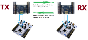
—Flow – None - When you press the Blue Button on TX kit you must see the red led (it is on X-NUCLEO-IDS01A4 board) on RX kit that change status.
On TX kit, if the RX kit send the ACK you must see the red led (on TX kit) that change status.
On other words, every time you press the Blue Button on TX kit you must see the red led (on TX kit and RX kit) that change status.
Press the Blue Botton on TX kit and the Red LEDs go ON (on both kit), press again the Blue Botton (on TX kit) and the Red LEDs go OFF, and so on.
On your PC you must see something like below.
ATTENTION:
The red led indicate only that the frame is trasmitted correctly.
–

– - If you go away with the TX kit, at a certain point the LEDs will no longer change status, this indicating that you are beyond the operating distance of the modules.
NOTE:
This application works at:
DATA RATE – 38,433 Kbps because the SPSGRF (Spirit1 module) is especially configured for get a best result at this Kbps.
FREQUENCY DEVIATION – 19,836 Khz
CHANNEL FILTER – 102,115 Khz
MODULATION – 2-GFSK1
Below the test on this P2P network.

Attention
How to get the SW for this project
Please send us an email and ask us the password for: P2P-SPIRIT1
Please specify also your country and your city, this are only for our personal statistics.
Get the SW clicking here, but remember to ask us the password for open it.
Some extra info concerning software of P2P
All the task in TX and RX mode, are developed for working in Interrupts Mode, in this way we free the STM32L0x do do something extra functions and/or task.
The idea was to automate the TX-RX-ACK process for reduce at the minimum the MCU time usage.
The communication from TX and RX is not encrypted so if you need to use this sw for transfer a sensible data we suggest to use the SPIRIT1 internal AES 128bit encryption co-processor or crypto library.
Inside the project there are a lot of files, some are very interesting to study.
We highlight the file below.
–
SPIRIT1.c
In this file there are the SPIRIT1 registers configuration and the address of the TX and RX kit ().
If you open the SPIRIT1.c present in the RX package at lines 187 … 197 there is the address of the RX board and the address of the TX board.

Look the registers maps at pg.92, in the SPIRIT1 data sheet.

Similar is the file SPIRIT1.c present in TX package at line 195…201, see below.

In the receiver (RX) we filter automatically the address of the packet that is received. See the box below.

If the address is equal to the receiver address, the SPIRIT1 accept the incoming package.
For do this is necessary set to 1 the bit n.3 of the register 0x4F, see above.
The value to write in the register 0x4F is:
0x48 -> 01001000
The max number of re-transmissions, in case of the TX don’t receive the ACK, is set to 3.
For set this value is necessary set the bit n.7..4 in the register n.0x52, to 0x3.
It is also necessary enable the automatic ACK, bit n.2 in the register n.0x52, must set to 1.
For configure the Modulation Type is necessary configure the register n.0x1B, see below.
–

For configure the DATA RATE is necessary the bit n.3…0 in the register n.0x1B in according to the formula shown below.
See the SPIRIT1 datasheet at pg.59

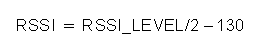
The RSSI is very important for know the intensity of the signal that you receive.
RSSI value is available after a packet received in the register n.0xC8
The formula for calculate the RSSI in dbm is below.
See the See the SPIRIT1 datasheet at pg.71
Important Note
In this version of SW we have enabled the ACK with Piggybacking.
See the SPIRIT1 data sheet at pg.68 and 94.
Thanks to this function, is possible send the ACK plus a return string (up to 10 characters), from the RX to the TX.
In practice you can tell to the TX, if what it has been received from the RX, is correct or not.
In our SW, there are two strings in main.c which are called:
uint8_t vectcTxBuff [15] = {'E', 'M', 'C', 'U', '.', 'E', 'U', '', '.', '.', '.', '\ 0', '\ 0', '\ 0'}; // 15 initial size
uint8_t vectcRxBuff [18];
If you change the vectcTxBuff [15] string in the RX module with:
uint8_t vectcTxBuff [15] = {'E', 'M', 'C', 'U', '.', 'x', 'U', '', '.', '.', '.', '\ 0', '\ 0', '\ 0'};
The RX highlight an error, see below.
The TX also shows a return string different from the one transmitted by it, see below.
Obviously, if you change the TX sw, you can highlight the error more explicitly.

CUBE-MX connections

NOTE:
- Use FIREFOX or CHROME for a clear view of the images present in this web site
- For enlarge the image press: CTRL +
For reduce the image press: CTRL –