–
The GPIOs has 16 interrupt lines.
All pins with same number are connected to line with same number.
They are multiplexed to one line.
Each line can trigger an interrupt on rising, falling or rising_falling edge on signal.
IMPORTANT: You can not use two pins on one line simultaneously.
Below there is an example of Interrupt pins, consult your STM32 Manual.
| Port Pins | Port Pins | Port Pins | Port Pins | Interrupt lines |
| PA0 | PB0 | ….. | Px0 | Line_0 |
| PA1 | PB1 | ….. | Px1 | Line_1 |
| PA2 | PB2 | ….. | Px2 | Line_2 |
| PA3 | PB3 | ….. | Px3 | Line_3 |
| PA4 | PB4 | ….. | Px4 | Line_4 |
| PA5 | PB5 | ….. | Px5 | Line_5 |
| PA6 | PB6 | ….. | Px6 | Line_6 |
| PA7 | PB7 | ….. | Px7 | Line_7 |
| PA8 | PB8 | ….. | Px8 | Line_8 |
| PA9 | PB9 | ….. | Px9 | Line_9 |
| PA10 | PB10 | ….. | Px10 | Line_10 |
| PA11 | PB11 | ….. | Px11 | Line_11 |
| PA12 | PB12 | ….. | Px12 | Line_12 |
| PA13 | PB13 | ….. | Px13 | Line_13 |
| PA14 | PB14 | ….. | Px14 | Line_14 |
| PA15 | PB15 | ….. | Px15 | Line_15 |
ATTENTION: in reality in the Cortex-Mx (STM32) we don’t have 16 external interrupt line, normally there are many less.
See the reference manual of the STM32 family that you need to use.
STM32F4 has 7 interrupt handlers for GPIO pins.
They are in table below:
| Irq | Handler | Description |
|---|---|---|
| EXTI0_IRQn | EXTI0_IRQHandler | Handler for pins connected to line 0 |
| EXTI1_IRQn | EXTI1_IRQHandler | Handler for pins connected to line 1 |
| EXTI2_IRQn | EXTI2_IRQHandler | Handler for pins connected to line 2 |
| EXTI3_IRQn | EXTI3_IRQHandler | Handler for pins connected to line 3 |
| EXTI4_IRQn | EXTI4_IRQHandler | Handler for pins connected to line 4 |
| EXTI9_5_IRQn | EXTI9_5_IRQHandler | Handler for pins connected to line 5 to 9 |
| EXTI15_10_IRQn | EXTI15_10_IRQHandler | Handler for pins connected to line 10 to 15 |
Interrupt Latency
The NVIC is designed for fast and efficient interrupt handling; on a Cortex-M4 you will reach the first line of C code in your interrupt routine after 12 cycles for a zero wait state memory system.
This interrupt latency is fully deterministic so from any point in the background (non-interrupt) code you will enter the interrupt with the same latency.
Multi-cycle instructions can be halted with no overhead and then resumed once the interrupt has finished.
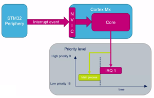
The External Interrupts are handled by the NVIC (nested vectored interrupt controller) peripheral.
If comes an interrupt, NVIC handle it and the Cortex-Mx core suspend the MAIN PROCESS and respond to the IRQ1.
At the end of the response at IRQ1, the core back to the MAIN PROCESS at the exactly position where it whas suspended before.
See the images below.
–

NVIC is the arbiter that decide the execution of interrupt based on the priority and sub-priority of the interrupt.
See below.

–

–

ATTENTION:
The priority below is available on M3 and M4 and on M7 there are even more possibilities.
On M0 and M0+ is available only PRE-EMPT priority

The below image represent the setup that you must do to use the EXTI (external interrupt input)

Now we will show how to configure two GPIO in Input in Interrupt mode.
For do this test we use the NUCLEO-F401RE board.
All is developed using a free tools that are: CUBE-MX and ATOLLIC compiler.
First run CUBE-MX and select the NUCLEO-F401RE board.
Attention, when you select the board NUCLEO-F401RE, at the end will appear a message box like below, plese choose YES (step n.6).
See below.

Now configure the GPIO PA8 and PA9 as shown below.
Pull-Up and External Interrupt Mode with Falling edge trigger detection
NOTE:
External Event Mode…
It’s used for wake up the MCU without generate an interrupt.

Now enable the INTERRUPT on PA8 and PA9.

Last but not least, is necessary configure the Cube-MX to generate the code for Atollic, see below.
 Generate the code and at this point you has a directory where inside there is the Atollic project and the Cube-MX configuration file.
The project directory in our case is name:
PA8_9Int
The root working directory is:
0_F4GPIOinter
See below.

Now start ATOLLIC by double click on the file named: .project
At startup, ATOLLIC request to choose the root working directory, in our case is:
0_F4GPIOinter
See below.

Now if you look in the file:
stm32f4xx_it.c
you must see the two functions that handle the external interrupts, see below.
/**
* @brief This function handles EXTI line[9:5] interrupts.
*/
void EXTI9_5_IRQHandler(void)
{
/* USER CODE BEGIN EXTI9_5_IRQn 0 */

/* USER CODE END EXTI9_5_IRQn 0 */
HAL_GPIO_EXTI_IRQHandler(GPIO_PIN_8); // Reset the PIN8 Interrupt
HAL_GPIO_EXTI_IRQHandler(GPIO_PIN_9); // Reset the PIN9 Interrupt
/* USER CODE BEGIN EXTI9_5_IRQn 1 */

/* USER CODE END EXTI9_5_IRQn 1 */
}

/**
* @brief This function handles EXTI line[15:10] interrupts.
*/
void EXTI15_10_IRQHandler(void)
{
/* USER CODE BEGIN EXTI15_10_IRQn 0 */

/* USER CODE END EXTI15_10_IRQn 0 */
HAL_GPIO_EXTI_IRQHandler(GPIO_PIN_13); // Reset the PIN13 Interrupt - Blue Button
/* USER CODE BEGIN EXTI15_10_IRQn 1 */

/* USER CODE END EXTI15_10_IRQn 1 */
}
Note also in the file:
main.c
in the function:
static void MX_GPIO_Init(void)
there is GPIO Interrupt inizializzation and also the NVIC inizializzation.
See below.
/** Configure pins as
        * Analog
        * Input
        * Output
        * EVENT_OUT
        * EXTI
*/
static void MX_GPIO_Init(void)
{

  GPIO_InitTypeDef GPIO_InitStruct;

  /* GPIO Ports Clock Enable */
  __HAL_RCC_GPIOC_CLK_ENABLE();
  __HAL_RCC_GPIOH_CLK_ENABLE();
  __HAL_RCC_GPIOA_CLK_ENABLE();
  __HAL_RCC_GPIOB_CLK_ENABLE();

  /*Configure GPIO pin Output Level */
  HAL_GPIO_WritePin(LD2_GPIO_Port, LD2_Pin, GPIO_PIN_RESET);

  /*Configure GPIO pin : B1_Pin - Blue Button*/
  GPIO_InitStruct.Pin = B1_Pin;
  GPIO_InitStruct.Mode = GPIO_MODE_IT_FALLING;
  GPIO_InitStruct.Pull = GPIO_NOPULL;
  HAL_GPIO_Init(B1_GPIO_Port, &GPIO_InitStruct);

  /*Configure GPIO pin : LD2_Pin */
  GPIO_InitStruct.Pin = LD2_Pin;
  GPIO_InitStruct.Mode = GPIO_MODE_OUTPUT_PP;
  GPIO_InitStruct.Pull = GPIO_NOPULL;
  GPIO_InitStruct.Speed = GPIO_SPEED_FREQ_LOW;
  HAL_GPIO_Init(LD2_GPIO_Port, &GPIO_InitStruct);

  /*Configure GPIO pins : PA8 PA9 */
  GPIO_InitStruct.Pin = GPIO_PIN_8|GPIO_PIN_9;
  GPIO_InitStruct.Mode = GPIO_MODE_IT_FALLING;
  GPIO_InitStruct.Pull = GPIO_PULLUP;
  HAL_GPIO_Init(GPIOA, &GPIO_InitStruct);

  /* EXTI interrupt init*/
  HAL_NVIC_SetPriority(EXTI9_5_IRQn, 0, 0);
  HAL_NVIC_EnableIRQ(EXTI9_5_IRQn);

  HAL_NVIC_SetPriority(EXTI15_10_IRQn, 0, 0);
  HAL_NVIC_EnableIRQ(EXTI15_10_IRQn);

}
Now for handle the interrupt we use the call back.
Open the file:
stm32f4xx_hal_gpio.c
and search (ctrl + f) the name:
__weak
See below.
For handle the interrupt we use the call back named:
HAL_GPIO_EXTI_Callback(uint16_t GPIO_Pin)

Now open the file: main.c
and insert from:
/* USER CODE BEGIN 4 */
and
/* USER CODE END 4 */
the below code.
void HAL_GPIO_EXTI_Callback(uint16_t GPIO_Pin)
{
	switch(GPIO_Pin)
		{
		case B1_Pin: // GPIO_PIN_13 is the Blue Button
			HAL_GPIO_TogglePin(LD2_GPIO_Port, LD2_Pin); // Green LED - GPIOA, GPIO_PIN_5
			break;
		case GPIO_PIN_8:
			HAL_GPIO_TogglePin(LD2_GPIO_Port, LD2_Pin); // Green LED - GPIOA, GPIO_PIN_5
			break;
		case GPIO_PIN_9:
			HAL_GPIO_TogglePin(LD2_GPIO_Port, LD2_Pin); // Green LED - GPIOA, GPIO_PIN_5
			break;
		}
}
Now if you press the Blue Button or connect to ground PA8 or PA9 you see the Green LED toggle it’s status.
Of course, for a good work, we suggest to insert a debounce time on all the input pins.
How to get the SW for this project
Please send us an email and ask us the password for: GPIOinterrupt
Please specify also your country and your city, this are only for our personal statistics.
Get the SW clicking here, but remember to ask us the password for open it.
NOTE:
For inport this project in your ATOLLIC read this note.
Thanks to Prof. Angelo Pietro Pennisi for it’s video that is here.
NOTE:
- Use FIREFOX or CHROME for a clear view of the images present in this web site
- For enlarge the image press: CTRL +
For reduce the image press: CTRL –
Useful Links