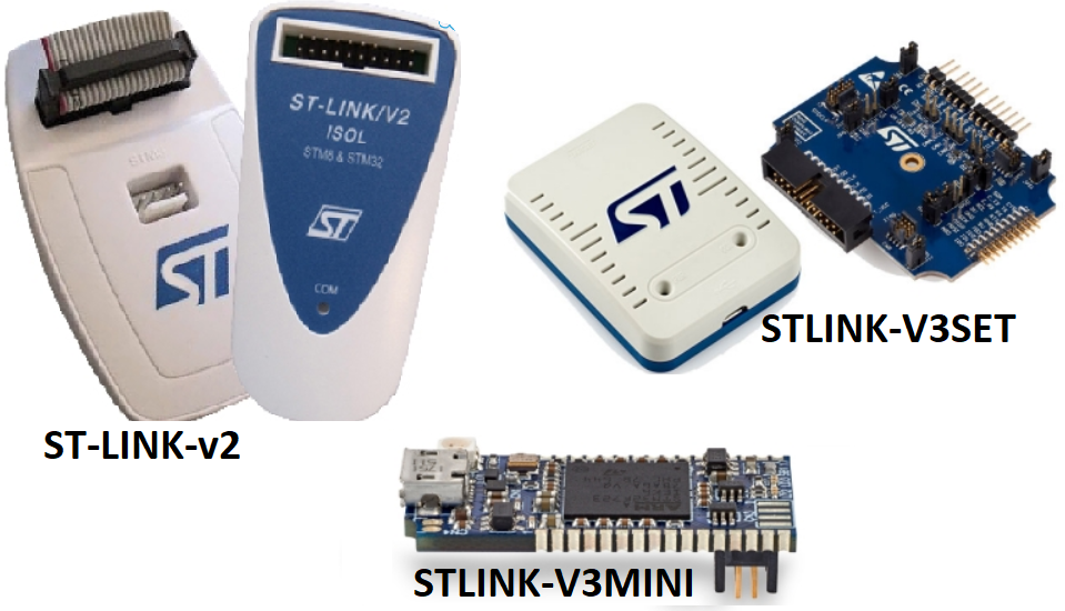
Above there are the ST-LINK tools available today (Nov.2019).
In this note we explain how to connect the ST-LINK-v2 to the STM8 for debugging and programming.
To use the ST-LINK-v2 (stand-alone emulator and programmer) to program or debug the STM8 the SWIM protocol must be used together with the STVP-STM8 (for program) STVD-STM8 (for debug) software package.
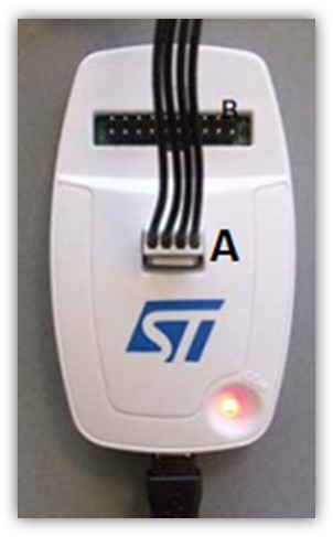
The signals must be taken from connector A of STLINK-v2, see image above and this manual (pg.9 / 10).
Physically the signals to be used are shown below (always from the manual above on pg.11)
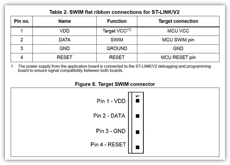
Importantly, your board must be powered because the VDD and GND signals on the programming connector (see fig.8 above) are only used as monitors.
All four wires must be connected (VDD, DATA, GND, RESET) using the shortest possible wiring.
If there were problems, we suggest putting two 10K resistors between VDD and DATA and between VDD and RESET.