ATTENTION:
this are obsolete products.
No longer support from STM.

- Introduction
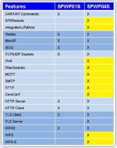
- Comparison between SPWF01Sx and SPWF04Sx
- SPWF04S User Integration Interface Modes
- SPWF04S SW Architecture Description
- Evaluation Board
- Host Interfaces
- FOTA (FW & SW update via WiFi network)
- Variable: console_enabled
- Firmware Package for SPWF04Sx modules
- Tutorial
Introduction
The SPWF04SA (integrated antenna) and the SPWF04SC (external antenna) intelligent Wi-Fi modules represent a plug-and-play and standalone 802.11 b/g/n solution for easy integration of wireless Internet connectivity features into existing or new connectivity products.
Configured around a single-chip 802.11 transceiver with integrated PA and comprehensive power management subsystem, and an STM32F4 microcontroller with an extensive GPIO suite, the modules also incorporate timing clocks and a voltage regulator.
The SPWF04Sx parts are released with an integrated full featured TCP/IP protocol stack with added application service capabilities and an integrated uPython scripting engine to enable custom application development within the module.
1 MB of the internal Flash is dedicated to store the user file system while an HW interface is provided to allow the usage of an external memory to extend the file system storage capabilities with no size limit.


Go on TOP
Comparison between SPWF01Sx and SPWF04Sx
Go on TOP
SPWF04S User Integration Interface Modes
The figure below summarize the possible integrations of a module SPWF04S in a user target application.
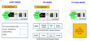
Go on TOP
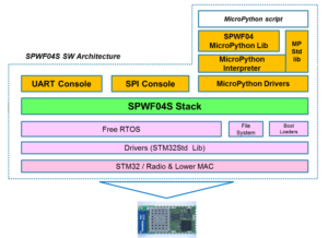
SPWF04S SW Architecture Description
The complete SW architecture of SPWF04S is showed in Figure below.
The Block Diagram of the SPWF04S Protocol Stack is shown below.
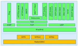
Go on TOP
Evaluation Board
- X-BOARD for the new SPWF04S is here
Go on TOP
Host Interfaces
SPWF04S supports two interfaces, UART and SPI, that allow connecting the module with an host processor.
The pins to be used in the two possible configurations are indicated in the Table below.
By default, SPWF04S works using the UART port with AT commands.
To switch on SPI the pin correspondent to GPIO[9] must be driven low at the boot time, that forces the device to handle incoming commands over SPI instead of over the UART.
-
- UART InterfaceSPWF04S can be interfaced with an external host using UART interface as shown in Figure 2. This configuration is used by default.
In particular there are 4 signals including RTS and CTS for HW Flow Control.
The UART baud rate is configurable in the 1200-921600 range of values. The default configuration is 115200/8/n/1 with Flow Control disabled.The figure below show the UART Connection with Host Device
–

- UART InterfaceSPWF04S can be interfaced with an external host using UART interface as shown in Figure 2. This configuration is used by default.
- SPI InterfaceThe SPWF04S can be interfaced, as a slave, with an external host by using the SPI interface as shown in Figure below.
In particular there are four SPI signals and an additional signal for host interrupt.
This Interrupt signal allows the SPI slave to alert the SPI master that it has data to send.
In turn, the SPI master needs to assert the GPIO connected to the SPWF04S chip select and to start the CLK signal to send data to the slave.Figure below show the SPI Connection with Host Device
–

Go on TOP
FOTA
FOTA is used for firmware (concerning the WiFi module) & software (concerning user program) update via WiFi network.
FOTA is available also in uPython.
See the commands: fsupdate and fwupdate
Go on TOP
console_enabled
• UART Interface (default operation)
“console_enabled = 1”
The UART console provides a user friendly interface built on a set of AT commands that allow an external Micro connected to the SPWF04 UART to access the functionalities integrated in SPWF04S device. UART is set as the module default interface.
• SPI Interface
“console_enabled = 0”
The Device can be connected as a slave to the SPI interface of an external Micro. Ad hoc SPI protocol and correspondent packet format are defined.
• MicroPython Scripting
“console_enabled = 2” – to use MicroPython together with At commands over UART,
”console_enabled = 3” – to use MicroPython only.
The Device implements a scripting methodology based on an integrated MicroPython interpreter.
MicroPython scripts can map a target application making unnecessary the integration of the Device with an external processor.
For configure the console_enabled use the command:
AT+S.SCFG=console_enabled,N -> N will be 0, 1, 2, 3
For see the value of the console_enabled use the command:
AT&V

Go on TOP
- Firmware Package for SPWF04Sx modules is here
- The last Firmware Package (1.1.0) for SPWF04Sx modules is here but is available only for AVNET-SILICA internal tests.
Go on TOP
Tutorial
- MQTT & TLS
Using AT command. In red the TLS linesat+s.mqttconn=xxxxxx.messaging.internetofthings.ibmcloud.com,443,/,1,use-token-auth,xxxxxxxxxxxxxxxxxx,d:xxxxxx:ST-Wifi-Module:STWifiModule,60,15,0,,<CR><LF> AT-S.Skip CA<CR><LF> AT-S.Loading:1:2<CR><LF> AT-S.On:0:0<CR><LF> AT-S.OK:17568:10<CR><LF>
Using uPython
from MQTT import * m=MQTT() m.init(login=('use-token-auth', 'xxxxxxxxxxxxxxxxxx'), ID='d:xxxxxx:ST-Wifi-Module:STWifiModule') m.connect(('xxxxxx.messaging.internetofthings.ibmcloud.com', 443), 1) - I2C scan
at+s.python

from pyb import I2C
from pyb import delay
i2c = I2C(3,I2C.MASTER)
i2c.init(I2C.MASTER,baudrate=20000)
#i2c.scan()
while True:
            #WHO_AM_I -> #indirizzo LPS22HB -> 0x5D / #WHO_AM_I (0x0F) -> B1
            #i2c.mem_read(1,0x5D,0x0F,addr_size=8)
            # configuro in one shot mode:  CTRL_REG1(10h) -> 0,CTRL_REG1(11h) -> 1
            i2c.mem_write(b'\x00',0x5D,0x10)
            i2c.mem_write(b'\x01',0x5D,0x11)
            #LEGGO PRESS_OUT_H,#LEGGO PRESS_OUT_L,#LEGGO PRESS_OUT_XL, concateno e divido per 4096 per ottenere il valore in mbar
            (int.from_bytes(i2c.mem_read(1,0x5D,0x28,addr_size=8)) + int.from_bytes(i2c.mem_read(1,0x5D,0x29,addr_size=8)) * 256 + int.from_bytes(i2c.mem_read(1,0x5D,0x2A,addr_size=8)) * 65536)/4096
            #WHO_AM_I -> #indirizzo HTS221 -> 0x5F / #WHO_AM_I (0x0F) -> BC
            #i2c.mem_read(1,0x5F,0x0F,addr_size=8)
            delay(1000)
Go on TOP